SSDs


TechInsights Publishes Preliminary Analysis of 3D XPoint Memory

TechInsights Publishes Preliminary Analysis of 3D XPoint Memory

Now that the Intel Optane Memory M.2 SSDs are readily available on the open market, anyone with an electron microscope and the skills to use it can begin to probe the secrets of 3D XPoint memory that Intel and Micron have been keeping tightly under wraps since announcing the new technology in August 2015. The reverse engineering experts at TechInsights have been doing just that, and they recently published their initial findings.

Die Size

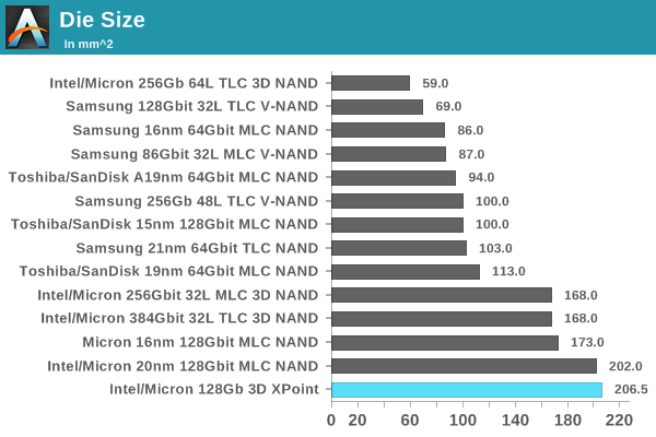
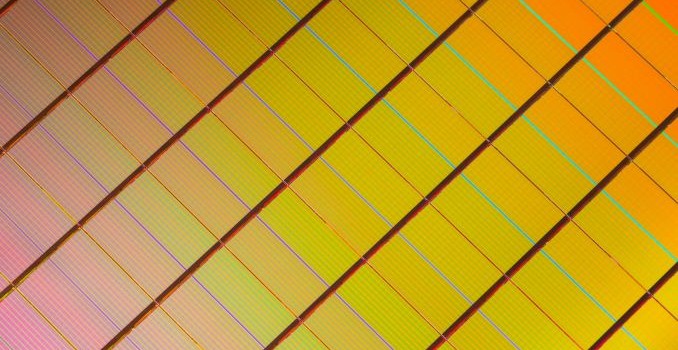
With some of the first high-resolution die photographs of 3D XPoint, TechInsights has provided precise measurements of the die size and memory density. The 128Gb 3D XPoint die is 206.5 mm2, much larger than is typical for modern NAND flash or DRAM but comparable to Intel’s 128Gb 20nm planar MLC NAND. A large total die size is typical for Intel and Micron, as they have historically not catered to the mobile market with their NAND flash while competitors like Samsung and Toshiba have strived to ensure their flash will physically fit in devices like smartphones. (That trend is changing with the introduction this year of 64-layer 3D NAND where Intel and Micron are producing both a larger 512Gb TLC part and a smaller 256Gb TLC part.)

Bit Density

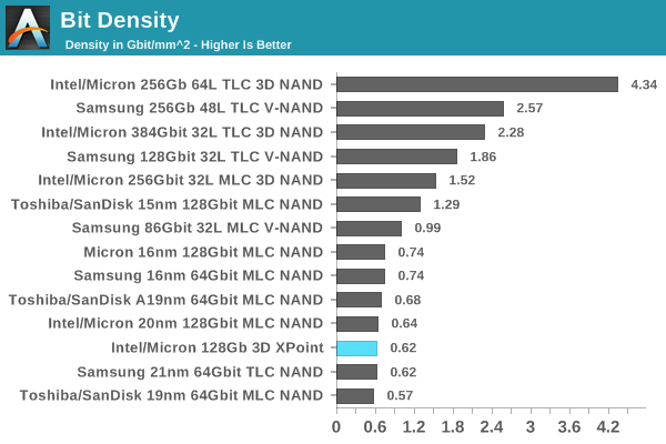
The Intel Optane SSD DC P4800X is using memory of similar density to the Intel SSD DC P3700 that it is displacing as the flagship of Intel’s SSD product line. When comparing similar chips, die size is a strong predictor of manufacturing cost, but 3D XPoint memory is quite different from NAND flash memory, both older planar NAND or newer 3D NAND. Still, there’s some value in noting that the P4800X is arriving with a price tag about 25% higher than the P3700 initially carried. This suggests that the manufacturing process for 3D XPoint is either more expensive than planar NAND or that 3D XPoint yields are not mature enough, but a lot of the markup can also be explained by the lack of high-performance competition for Optane SSDs.

TechInsights calculates that 91.4% of the 3D XPoint die area is occupied by the memory array itself. This is a much higher figure than for NAND flash, where the record is 84.9% for Intel/Micron 3D NAND with its “CMOS under the array” design that puts a large portion of the peripheral circuitry underneath the memory array instead of alongside. Samsung’s current 48-layer 3D V-NAND manages an array efficiency of just 70%, and 3D NAND from Toshiba and SK Hynix has been comparable. This means that once Intel gets around to increasing they layer count in future generations of 3D XPoint memory, they should be able to get much closer to the ideal capacity scaling than 3D NAND memory can currently achieve.

The analysis from TechInsights confirms that 3D XPoint memory is manufactured using a 20nm process, with the same pitch in both the bitline and wordline directions of the memory array. The DRAM market is only just moving beyond this milestone, so comparing the density of 3D XPoint to current DRAM highlights the fundamental capacity advantage 3D XPoint enjoys: around 4.5 times higher density compared to typical 20nm DRAM, and about 3.3 times higher than the most advanced 1Xnm DDR4 on the market. This gap is likely to widen with future generations of 3D XPoint.

The materials and construction of an individual 3D XPoint memory cell have not been fully analyzed, but it appears to be a phase change memory element with a doped chalcogenide selector switch. The 3D XPoint memory array is constructed between the fourth and fifth metal interconnect layers above the silicon die.

TechInsights Publishes Preliminary Analysis of 3D XPoint Memory

TechInsights Publishes Preliminary Analysis of 3D XPoint Memory

Now that the Intel Optane Memory M.2 SSDs are readily available on the open market, anyone with an electron microscope and the skills to use it can begin to probe the secrets of 3D XPoint memory that Intel and Micron have been keeping tightly under wraps since announcing the new technology in August 2015. The reverse engineering experts at TechInsights have been doing just that, and they recently published their initial findings.

Die Size

With some of the first high-resolution die photographs of 3D XPoint, TechInsights has provided precise measurements of the die size and memory density. The 128Gb 3D XPoint die is 206.5 mm2, much larger than is typical for modern NAND flash or DRAM but comparable to Intel’s 128Gb 20nm planar MLC NAND. A large total die size is typical for Intel and Micron, as they have historically not catered to the mobile market with their NAND flash while competitors like Samsung and Toshiba have strived to ensure their flash will physically fit in devices like smartphones. (That trend is changing with the introduction this year of 64-layer 3D NAND where Intel and Micron are producing both a larger 512Gb TLC part and a smaller 256Gb TLC part.)

Bit Density

The Intel Optane SSD DC P4800X is using memory of similar density to the Intel SSD DC P3700 that it is displacing as the flagship of Intel’s SSD product line. When comparing similar chips, die size is a strong predictor of manufacturing cost, but 3D XPoint memory is quite different from NAND flash memory, both older planar NAND or newer 3D NAND. Still, there’s some value in noting that the P4800X is arriving with a price tag about 25% higher than the P3700 initially carried. This suggests that the manufacturing process for 3D XPoint is either more expensive than planar NAND or that 3D XPoint yields are not mature enough, but a lot of the markup can also be explained by the lack of high-performance competition for Optane SSDs.

TechInsights calculates that 91.4% of the 3D XPoint die area is occupied by the memory array itself. This is a much higher figure than for NAND flash, where the record is 84.9% for Intel/Micron 3D NAND with its “CMOS under the array” design that puts a large portion of the peripheral circuitry underneath the memory array instead of alongside. Samsung’s current 48-layer 3D V-NAND manages an array efficiency of just 70%, and 3D NAND from Toshiba and SK Hynix has been comparable. This means that once Intel gets around to increasing they layer count in future generations of 3D XPoint memory, they should be able to get much closer to the ideal capacity scaling than 3D NAND memory can currently achieve.

The analysis from TechInsights confirms that 3D XPoint memory is manufactured using a 20nm process, with the same pitch in both the bitline and wordline directions of the memory array. The DRAM market is only just moving beyond this milestone, so comparing the density of 3D XPoint to current DRAM highlights the fundamental capacity advantage 3D XPoint enjoys: around 4.5 times higher density compared to typical 20nm DRAM, and about 3.3 times higher than the most advanced 1Xnm DDR4 on the market. This gap is likely to widen with future generations of 3D XPoint.

The materials and construction of an individual 3D XPoint memory cell have not been fully analyzed, but it appears to be a phase change memory element with a doped chalcogenide selector switch. The 3D XPoint memory array is constructed between the fourth and fifth metal interconnect layers above the silicon die.

NVMe 1.3 Specification Published With New Features For Client And Enterprise SSDs

NVMe 1.3 Specification Published With New Features For Client And Enterprise SSDs

The first major update to the NVMe storage interface specification in almost two and a half years has been published, standardizing many new features and helping set the course for the SSD market. Version 1.2 of the NVMe specification was ratified in November 2014 and since then there have been numerous corrections and clarifications but the only significant new feature added were the enterprise-oriented NVMe over Fabrics and NVMe Management Interface specifications. The NVMe 1.3 specification ratified last month and published earlier this month brings many new features for both client and server use cases. As with previous updates to the standard, most of the new features are optional but will probably see widespread adoption in their relevant market segments over the next few years. Several of the new NVMe features are based on existing features of other storage interfaces and protocol such as eMMC and ATA. Here are some of the most interesting new features:

Device Self Tests

Much like the SMART self-test capabilities found on ATA drives, NVMe now defines an optional interface for the host system to instruct the drive to perform a self test. The details of what is tested are left up to the drive vendor, but drives should implement both short (no more than two minutes) and extended self tests that may include reading and writing to all or part of the storage media but must preserve user data and the drive must remain operational during the test (either by performing the test in the background or by pausing the test to service other IO requests). For the extended test, drives must offer an estimate of how long the test will take and provide a progress indicator during the test.

Boot Partitions

Borrowing a feature from eMMC, NVMe 1.3 introduces support for boot partitions that can be accessed using a minimal subset of the NVMe protocol, without requiring the host to allocate and configure the admin or command queues. Boot Partitions are intended to reduce or eliminate the need for the host system to include another storage device such as a SPI flash to store the boot firmware (such as a UEFI implementation). Drives implementing the Boot Partition feature will include a pair of boot partitions to allow for safe firmware updates that write to the secondary partition and verify the data before swapping which partition is active.

The boot partition feature is unlikely to be useful or ever implemented on user-upgradable drives, but it provides an opportunity for cost savings in embedded systems like smartphones and tablets, which are increasingly turning to NVMe BGA SSDs for high-performance storage. The boot partitions can also be made tamper resistant using the Replay Protected Memory Block feature that was introduced in NVMe 1.2.  

Sanitize

The new optional Sanitize feature set is another import from other storage standards; it is already available for SATA and SAS drives. The Sanitize command is an alternative to existing secure erase capabilities that makes stronger guarantees about data security by ensuring that user data is not only removed from the drive’s media but from all of its caches, and the Controller Memory Buffer (if supported) is also wiped. The Sanitize command also lets the host be more explicit in specifying how the data is destroyed: through block erase operations, overwriting, or destroying the encryption key. (Drives may not support all three methods.) Current NVMe SSDs offer secure erase functionality through the Format NVM command, which exists primarily to support switching the block format from eg. 512 byte sectors to 4kB sectors, but can also optionally perform a secure erase in the process. While the Format NVM command’s scope can be restricted to a particular namespace attached to the NVMe controller, the Sanitize command is always global and wipes the entire drive (save for boot partitions and the replay protected memory block, if implemented).

Virtualization

Previous versions of the NVMe specification allowed for controllers to support virtualization through Single Root I/O Virtualization (SR-IOV) but left the implementation details unspecified. Version 1.3 introduces a standard virtualization feature set that defines how SR-IOV capabilities can be configured and used. NVMe SSDs supporting the new virtualization enhancements will expose a primary controller as a SR-IOV physical function and one or more secondary controllers as SR-IOV virtual functions that can be assigned to virtual machines. (Strictly speaking, drives could implement the NVMe virtualization enhancements without supporting SR-IOV, but this is unlikely to happen.) The SSDs will have a pool of flexible resources (completion queues, submission queues and MSI-X interrupt vectors) that can be allocated to the drive’s primary or secondary controllers.
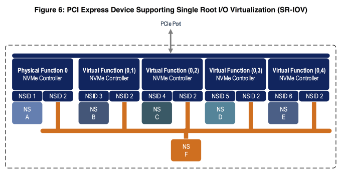
The NVMe virtualization enhancements greatly expand the usefulness of the existing NVMe namespace management features. So far, drives supporting multiple namespaces have been quite rare so the namespace features have mostly applied to multipath and NVMe over Fabrics use cases. Now, a single drive can use multiple namespaces to partition its storage among several virtual controllers assigned to different VMs, with the potential for namespaces to be exclusive or shared among VMs, all without requiring any changes to the NVMe drivers in the guest operating systems and without requiring the hypervisor to implement its own volume management layer.

Namespace Optimal IO Boundary

NVMe allows SSDs to support multiple sector sizes through the Format NVM command. Most SSDs default to 512-byte logical blocks but also support 4kB logical blocks, often with better performance. However, for flash-based SSDs, neither common sector size reflects the real page or block sizes of the underlying flash memory. Nobody is particularly interested in switching to the 16kB or larger sector sizes that would be necessary to match page sizes of modern 3D NAND flash, but there is potential for better performance if operating systems align I/O to the real page size. NVMe 1.3 introduces a Namespace Optimal IO Boundary field that provides exactly this performance hint to the host system, expressed as a multiple of the sector size (eg. 512B or 4kB).

Directives and Streams

The new feature that may prove to have the biggest long-term impact is NVMe’s Directives support, a generic framework for the controller and host system to exchange extra metadata in the headers of ordinary NVMe commands. For now, the only type of directive supported for ordinary IO commands is the Streams directive. Defined only for write commands, the streams directive allows the host to tag operations as related, such as originating from the same process or virtual machine. This serves as a hint to the controller about how to store that data on a physical level. For example, if multiple streams are actively writing simultaneously, the controller would probably want to write data from each stream contiguously rather than interleave writes from multiple streams into writes to the same physical page erase block. This can lead to more consistent write performance for multithreaded workloads, better prefetching for reads, and lower write amplification.

Non-Operational Power State Permissive Mode

NVMe power management is far more flexible than what SATA drives support. NVMe drives can declare several different power states including multiple operational and non-operational idle states. The drive can provide the host with information about the maximum power draw in each state, the latency to enter and leave each state, and the relative performance of the various operational power states. For drives supporting the optional Autonomous Power State Transitions feature (APST) introduced in NVMe 1.1, the host system can in turn provide the drive with rules about how long it should wait before descending to the next lower power state. NVMe 1.3 provides two significant enhancements to power management. The first is a very simple but crucial switch controlling whether a drive in an idle state may exceed the idle power limits to perform background processing like garbage collection. Battery-powered devices seeking to maximize standby time would likely want to disable this permissive mode. Systems that are not operating under strict power limits and are merely trying to minimize unnecessary power use without prohibiting garbage collection would likely want to enable permissive mode rather than leave the drive in a low-power operational state.

Host Controlled Thermal Management

The second major addition to the NVMe power management feature set is Host Controlled Thermal Management. Until now, the temperatures at which NVMe SSDs engage thermal throttling have been entirely model-specific and are not exposed to the host system. The new host controlled thermal management feature allows the host system to specify two temperature thresholds at which the drive should perform light and heavy throttling to reduce the drive’s temperature. Most of the details of thermal throttling are still left up to the vendor, including how the drive’s various temperature sensors are combined to form the Composite Temperature that the thresholds apply to, and the hysteresis of the throttling (how far below the threshold the temperature must fall before throttling ceases). Drives will continue to include their own built-in temperature limits to prevent damage, but now compact machines like smartphones, tablets and ultrabooks can prevent their SSD from raising other components to undesirable temperatures.

NVMe 1.3 Specification Published With New Features For Client And Enterprise SSDs

NVMe 1.3 Specification Published With New Features For Client And Enterprise SSDs

The first major update to the NVMe storage interface specification in almost two and a half years has been published, standardizing many new features and helping set the course for the SSD market. Version 1.2 of the NVMe specification was ratified in November 2014 and since then there have been numerous corrections and clarifications but the only significant new feature added were the enterprise-oriented NVMe over Fabrics and NVMe Management Interface specifications. The NVMe 1.3 specification ratified last month and published earlier this month brings many new features for both client and server use cases. As with previous updates to the standard, most of the new features are optional but will probably see widespread adoption in their relevant market segments over the next few years. Several of the new NVMe features are based on existing features of other storage interfaces and protocol such as eMMC and ATA. Here are some of the most interesting new features:

Device Self Tests

Much like the SMART self-test capabilities found on ATA drives, NVMe now defines an optional interface for the host system to instruct the drive to perform a self test. The details of what is tested are left up to the drive vendor, but drives should implement both short (no more than two minutes) and extended self tests that may include reading and writing to all or part of the storage media but must preserve user data and the drive must remain operational during the test (either by performing the test in the background or by pausing the test to service other IO requests). For the extended test, drives must offer an estimate of how long the test will take and provide a progress indicator during the test.

Boot Partitions

Borrowing a feature from eMMC, NVMe 1.3 introduces support for boot partitions that can be accessed using a minimal subset of the NVMe protocol, without requiring the host to allocate and configure the admin or command queues. Boot Partitions are intended to reduce or eliminate the need for the host system to include another storage device such as a SPI flash to store the boot firmware (such as a UEFI implementation). Drives implementing the Boot Partition feature will include a pair of boot partitions to allow for safe firmware updates that write to the secondary partition and verify the data before swapping which partition is active.

The boot partition feature is unlikely to be useful or ever implemented on user-upgradable drives, but it provides an opportunity for cost savings in embedded systems like smartphones and tablets, which are increasingly turning to NVMe BGA SSDs for high-performance storage. The boot partitions can also be made tamper resistant using the Replay Protected Memory Block feature that was introduced in NVMe 1.2.  

Sanitize

The new optional Sanitize feature set is another import from other storage standards; it is already available for SATA and SAS drives. The Sanitize command is an alternative to existing secure erase capabilities that makes stronger guarantees about data security by ensuring that user data is not only removed from the drive’s media but from all of its caches, and the Controller Memory Buffer (if supported) is also wiped. The Sanitize command also lets the host be more explicit in specifying how the data is destroyed: through block erase operations, overwriting, or destroying the encryption key. (Drives may not support all three methods.) Current NVMe SSDs offer secure erase functionality through the Format NVM command, which exists primarily to support switching the block format from eg. 512 byte sectors to 4kB sectors, but can also optionally perform a secure erase in the process. While the Format NVM command’s scope can be restricted to a particular namespace attached to the NVMe controller, the Sanitize command is always global and wipes the entire drive (save for boot partitions and the replay protected memory block, if implemented).

Virtualization

Previous versions of the NVMe specification allowed for controllers to support virtualization through Single Root I/O Virtualization (SR-IOV) but left the implementation details unspecified. Version 1.3 introduces a standard virtualization feature set that defines how SR-IOV capabilities can be configured and used. NVMe SSDs supporting the new virtualization enhancements will expose a primary controller as a SR-IOV physical function and one or more secondary controllers as SR-IOV virtual functions that can be assigned to virtual machines. (Strictly speaking, drives could implement the NVMe virtualization enhancements without supporting SR-IOV, but this is unlikely to happen.) The SSDs will have a pool of flexible resources (completion queues, submission queues and MSI-X interrupt vectors) that can be allocated to the drive’s primary or secondary controllers.

The NVMe virtualization enhancements greatly expand the usefulness of the existing NVMe namespace management features. So far, drives supporting multiple namespaces have been quite rare so the namespace features have mostly applied to multipath and NVMe over Fabrics use cases. Now, a single drive can use multiple namespaces to partition its storage among several virtual controllers assigned to different VMs, with the potential for namespaces to be exclusive or shared among VMs, all without requiring any changes to the NVMe drivers in the guest operating systems and without requiring the hypervisor to implement its own volume management layer.

Namespace Optimal IO Boundary

NVMe allows SSDs to support multiple sector sizes through the Format NVM command. Most SSDs default to 512-byte logical blocks but also support 4kB logical blocks, often with better performance. However, for flash-based SSDs, neither common sector size reflects the real page or block sizes of the underlying flash memory. Nobody is particularly interested in switching to the 16kB or larger sector sizes that would be necessary to match page sizes of modern 3D NAND flash, but there is potential for better performance if operating systems align I/O to the real page size. NVMe 1.3 introduces a Namespace Optimal IO Boundary field that provides exactly this performance hint to the host system, expressed as a multiple of the sector size (eg. 512B or 4kB).

Directives and Streams

The new feature that may prove to have the biggest long-term impact is NVMe’s Directives support, a generic framework for the controller and host system to exchange extra metadata in the headers of ordinary NVMe commands. For now, the only type of directive supported for ordinary IO commands is the Streams directive. Defined only for write commands, the streams directive allows the host to tag operations as related, such as originating from the same process or virtual machine. This serves as a hint to the controller about how to store that data on a physical level. For example, if multiple streams are actively writing simultaneously, the controller would probably want to write data from each stream contiguously rather than interleave writes from multiple streams into writes to the same physical page erase block. This can lead to more consistent write performance for multithreaded workloads, better prefetching for reads, and lower write amplification.

Non-Operational Power State Permissive Mode

NVMe power management is far more flexible than what SATA drives support. NVMe drives can declare several different power states including multiple operational and non-operational idle states. The drive can provide the host with information about the maximum power draw in each state, the latency to enter and leave each state, and the relative performance of the various operational power states. For drives supporting the optional Autonomous Power State Transitions feature (APST) introduced in NVMe 1.1, the host system can in turn provide the drive with rules about how long it should wait before descending to the next lower power state. NVMe 1.3 provides two significant enhancements to power management. The first is a very simple but crucial switch controlling whether a drive in an idle state may exceed the idle power limits to perform background processing like garbage collection. Battery-powered devices seeking to maximize standby time would likely want to disable this permissive mode. Systems that are not operating under strict power limits and are merely trying to minimize unnecessary power use without prohibiting garbage collection would likely want to enable permissive mode rather than leave the drive in a low-power operational state.

Host Controlled Thermal Management

The second major addition to the NVMe power management feature set is Host Controlled Thermal Management. Until now, the temperatures at which NVMe SSDs engage thermal throttling have been entirely model-specific and are not exposed to the host system. The new host controlled thermal management feature allows the host system to specify two temperature thresholds at which the drive should perform light and heavy throttling to reduce the drive’s temperature. Most of the details of thermal throttling are still left up to the vendor, including how the drive’s various temperature sensors are combined to form the Composite Temperature that the thresholds apply to, and the hysteresis of the throttling (how far below the threshold the temperature must fall before throttling ceases). Drives will continue to include their own built-in temperature limits to prevent damage, but now compact machines like smartphones, tablets and ultrabooks can prevent their SSD from raising other components to undesirable temperatures.
NVMe 1.3 Specification Published With New Features For Client And Enterprise SSDs

NVMe 1.3 Specification Published With New Features For Client And Enterprise SSDs

The first major update to the NVMe storage interface specification in almost two and a half years has been published, standardizing many new features and helping set the course for the SSD market. Version 1.2 of the NVMe specification was ratified in November 2014 and since then there have been numerous corrections and clarifications but the only significant new feature added were the enterprise-oriented NVMe over Fabrics and NVMe Management Interface specifications. The NVMe 1.3 specification ratified last month and published earlier this month brings many new features for both client and server use cases. As with previous updates to the standard, most of the new features are optional but will probably see widespread adoption in their relevant market segments over the next few years. Several of the new NVMe features are based on existing features of other storage interfaces and protocol such as eMMC and ATA. Here are some of the most interesting new features:

Device Self Tests

Much like the SMART self-test capabilities found on ATA drives, NVMe now defines an optional interface for the host system to instruct the drive to perform a self test. The details of what is tested are left up to the drive vendor, but drives should implement both short (no more than two minutes) and extended self tests that may include reading and writing to all or part of the storage media but must preserve user data and the drive must remain operational during the test (either by performing the test in the background or by pausing the test to service other IO requests). For the extended test, drives must offer an estimate of how long the test will take and provide a progress indicator during the test.

Boot Partitions

Borrowing a feature from eMMC, NVMe 1.3 introduces support for boot partitions that can be accessed using a minimal subset of the NVMe protocol, without requiring the host to allocate and configure the admin or command queues. Boot Partitions are intended to reduce or eliminate the need for the host system to include another storage device such as a SPI flash to store the boot firmware (such as a UEFI implementation). Drives implementing the Boot Partition feature will include a pair of boot partitions to allow for safe firmware updates that write to the secondary partition and verify the data before swapping which partition is active.

The boot partition feature is unlikely to be useful or ever implemented on user-upgradable drives, but it provides an opportunity for cost savings in embedded systems like smartphones and tablets, which are increasingly turning to NVMe BGA SSDs for high-performance storage. The boot partitions can also be made tamper resistant using the Replay Protected Memory Block feature that was introduced in NVMe 1.2.  

Sanitize

The new optional Sanitize feature set is another import from other storage standards; it is already available for SATA and SAS drives. The Sanitize command is an alternative to existing secure erase capabilities that makes stronger guarantees about data security by ensuring that user data is not only removed from the drive’s media but from all of its caches, and the Controller Memory Buffer (if supported) is also wiped. The Sanitize command also lets the host be more explicit in specifying how the data is destroyed: through block erase operations, overwriting, or destroying the encryption key. (Drives may not support all three methods.) Current NVMe SSDs offer secure erase functionality through the Format NVM command, which exists primarily to support switching the block format from eg. 512 byte sectors to 4kB sectors, but can also optionally perform a secure erase in the process. While the Format NVM command’s scope can be restricted to a particular namespace attached to the NVMe controller, the Sanitize command is always global and wipes the entire drive (save for boot partitions and the replay protected memory block, if implemented).

Virtualization

Previous versions of the NVMe specification allowed for controllers to support virtualization through Single Root I/O Virtualization (SR-IOV) but left the implementation details unspecified. Version 1.3 introduces a standard virtualization feature set that defines how SR-IOV capabilities can be configured and used. NVMe SSDs supporting the new virtualization enhancements will expose a primary controller as a SR-IOV physical function and one or more secondary controllers as SR-IOV virtual functions that can be assigned to virtual machines. (Strictly speaking, drives could implement the NVMe virtualization enhancements without supporting SR-IOV, but this is unlikely to happen.) The SSDs will have a pool of flexible resources (completion queues, submission queues and MSI-X interrupt vectors) that can be allocated to the drive’s primary or secondary controllers.

The NVMe virtualization enhancements greatly expand the usefulness of the existing NVMe namespace management features. So far, drives supporting multiple namespaces have been quite rare so the namespace features have mostly applied to multipath and NVMe over Fabrics use cases. Now, a single drive can use multiple namespaces to partition its storage among several virtual controllers assigned to different VMs, with the potential for namespaces to be exclusive or shared among VMs, all without requiring any changes to the NVMe drivers in the guest operating systems and without requiring the hypervisor to implement its own volume management layer.

Namespace Optimal IO Boundary

NVMe allows SSDs to support multiple sector sizes through the Format NVM command. Most SSDs default to 512-byte logical blocks but also support 4kB logical blocks, often with better performance. However, for flash-based SSDs, neither common sector size reflects the real page or block sizes of the underlying flash memory. Nobody is particularly interested in switching to the 16kB or larger sector sizes that would be necessary to match page sizes of modern 3D NAND flash, but there is potential for better performance if operating systems align I/O to the real page size. NVMe 1.3 introduces a Namespace Optimal IO Boundary field that provides exactly this performance hint to the host system, expressed as a multiple of the sector size (eg. 512B or 4kB).

Directives and Streams

The new feature that may prove to have the biggest long-term impact is NVMe’s Directives support, a generic framework for the controller and host system to exchange extra metadata in the headers of ordinary NVMe commands. For now, the only type of directive supported for ordinary IO commands is the Streams directive. Defined only for write commands, the streams directive allows the host to tag operations as related, such as originating from the same process or virtual machine. This serves as a hint to the controller about how to store that data on a physical level. For example, if multiple streams are actively writing simultaneously, the controller would probably want to write data from each stream contiguously rather than interleave writes from multiple streams into writes to the same physical page erase block. This can lead to more consistent write performance for multithreaded workloads, better prefetching for reads, and lower write amplification.

Non-Operational Power State Permissive Mode

NVMe power management is far more flexible than what SATA drives support. NVMe drives can declare several different power states including multiple operational and non-operational idle states. The drive can provide the host with information about the maximum power draw in each state, the latency to enter and leave each state, and the relative performance of the various operational power states. For drives supporting the optional Autonomous Power State Transitions feature (APST) introduced in NVMe 1.1, the host system can in turn provide the drive with rules about how long it should wait before descending to the next lower power state. NVMe 1.3 provides two significant enhancements to power management. The first is a very simple but crucial switch controlling whether a drive in an idle state may exceed the idle power limits to perform background processing like garbage collection. Battery-powered devices seeking to maximize standby time would likely want to disable this permissive mode. Systems that are not operating under strict power limits and are merely trying to minimize unnecessary power use without prohibiting garbage collection would likely want to enable permissive mode rather than leave the drive in a low-power operational state.

Host Controlled Thermal Management

The second major addition to the NVMe power management feature set is Host Controlled Thermal Management. Until now, the temperatures at which NVMe SSDs engage thermal throttling have been entirely model-specific and are not exposed to the host system. The new host controlled thermal management feature allows the host system to specify two temperature thresholds at which the drive should perform light and heavy throttling to reduce the drive’s temperature. Most of the details of thermal throttling are still left up to the vendor, including how the drive’s various temperature sensors are combined to form the Composite Temperature that the thresholds apply to, and the hysteresis of the throttling (how far below the threshold the temperature must fall before throttling ceases). Drives will continue to include their own built-in temperature limits to prevent damage, but now compact machines like smartphones, tablets and ultrabooks can prevent their SSD from raising other components to undesirable temperatures.