Cases/Cooling/PSUs


Antec Reveals the Signature S10 Premium Tower Case

Antec Reveals the Signature S10 Premium Tower Case

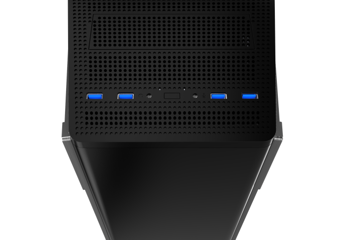
That Antec designed a new case may not really sound like news. After all, cases are the primary focus of the company, which offers dozens of models. However, this particular release is of special interest as the company has overhauled their lineup with a new flagship case, the Signature S10, a unique tower case of massive proportions. Meant to be Antec’s engineering pinnacle, the Signature S10 is an aggressive combination of advanced thermal performance, versatility, and elegant aesthetics.

Measuring 60 cm tall and 59 cm deep (23.7″ × 23.2″), the Signature S10 is one of the largest tower cases in existence. It also weights about 18 kg, making it a very heavy case that is certainly not designed for frequent movement. Still, the proportions of a case alone are not stimulating and not what is unique about this particular release. What is perhaps the most important point of the Signature S10 is that it features Antec’s patented three chamber design internal architecture.

Exactly as the name suggests, the three chamber design architecture splits the interior of the Signature S10 into three compartments. The entire front of the case is reserved for hard disk drives, the bottom compartment is shared between the PSU and five 2.5″ device trays, and the primary compartment is reserved for the main system alone. Note that, despite its size, the Signature S10 does not have any 5.25″ drive bays, so the idea of an optical drive is truly dead for this case. However, there is a slot for a short 5.25″ device (fan controller, card reader, etc.). The chassis is most likely made out of SECC steel and the buyer is given the choice between aluminum and smoked tempered glass doors for the side panels. If Antec’s press release is accurate and we are talking about real glass, not Plexiglass, that would be a sight to behold.

As the Signature S10 is intended to be Antec’s engineering pinnacle, the stock cooling of the case is intense. The very architecture of the case is supposed to aid thermal performance, forcing top-down airflow. There are seven stock fans, five 120 mm and two 140 mm, preinstalled into the Signature S10, the models and specifications of which are unknown at this point of time. To limit the insertion of dust, Antec installed micromesh air filters to each individual chamber.  

Obviously, Antec is trying to combine the very elegant appearance of the Signature series with outstanding thermal performance and expandability options, pitching the case as a good match for advanced gaming systems and workstations. Meanwhile it seems as Antec put every bit of their technology on the Signature S10, and the retail price reflects that, as the MSRP is just shy of $500. Consequently the potential market of the Signature S10 is going to be very small (if not very elite) limited to the most hardcore of enthusiasts who are willing to pay a very hefty price in order to combine elegant aesthetics and quality with thermal performance.

Corsair unleashes the Bulldog DIY 4K Gaming PC

Corsair unleashes the Bulldog DIY 4K Gaming PC

Corsair certainly is a company that is not afraid of diversification and has proved that multiple times in the past. They started as a memory products manufacturer, diversified into the power, case and cooling market segments and today they even have their own gaming division.

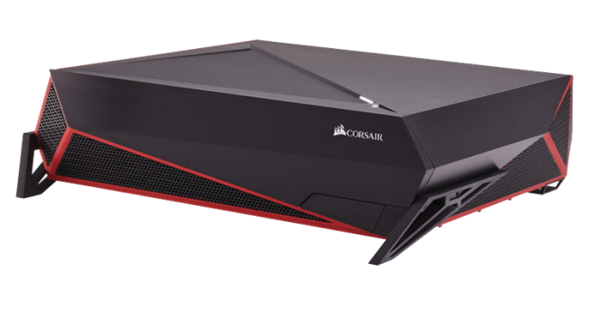
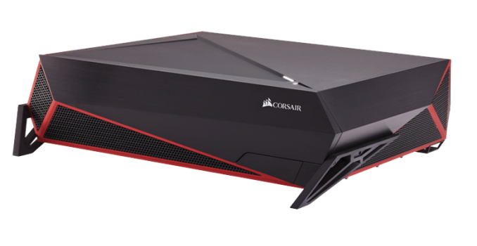
With a company as active as Corsair is, their latest move was no surprise to us. Corsair combined their knowledge of chassis design and thermal performance, used their industry contacts and brought about the creation of the Bulldog, a DIY 4K Gaming PC designed to fit into living rooms.

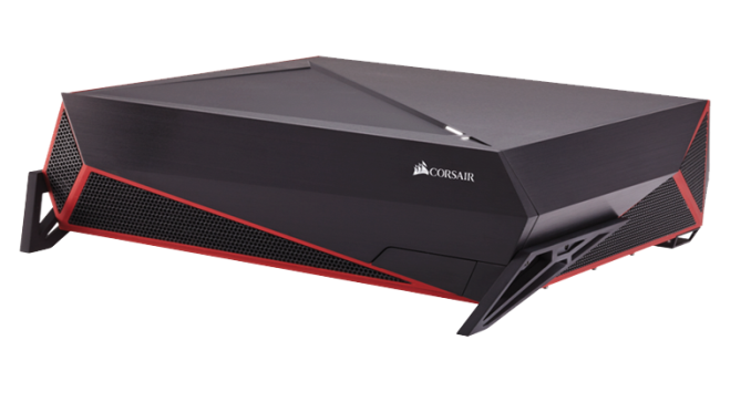
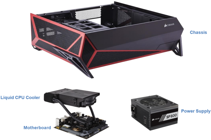
The Bulldog is the combination of a desktop PC case styled to appear as a gaming console with a 600W SFX power supply, a liquid cooler for the CPU and an ITX motherboard. Corsair’s aim was to reduce a very high performance gaming PC to fit within the dimensions of a gaming console. In order to do that, they managed to fit dual liquid cooling systems (one for the CPU and, optionally, one for the GPU) and a high output SFX PSU into the desktop chassis. In terms of size, the Bulldog is relatively small but not too small, as it had to be tall enough for a high-end graphics card to fit.

The base configuration of the Bulldog includes the case, the ITX motherboard, the H5SF CPU liquid cooler and the 600W SFX power supply. It starts with a MSRP of $399, which seems a little steep at first but it is not really overpriced considering the specs of the motherboard. We are not aware of very specific details regarding the motherboard that is installed in the Bulldog, but it will support DDR4 RAM, USB 3.1, 7.1 audio, Gigabit Ethernet and WiFi. (It’s worth noting that at this point, the only mini-ITX motherboard that can support DDR4 is the ASRock X99E-ITX, but in the pictures provided by Corsair the board used seems to be a DDR3 based ASUS. It doesn’t take much to pinpoint that the Bulldog is mostly likely aimed for a future DDR4 capable platform, or currently just for the ASRock motherboard if Corsair wishes to pursue the DDR4 route exclusively.) Corsair has also collaborated with NVIDIA and MSI to create drop-in ready liquid cooled variations of the Geforce GTX Titan X, GTX 980, GTX 980 Ti and GTX 970. Combinations of the Corsair H55 liquid AIO cooler and the HG10 graphics card cooling bracket may also be used.

Corsair’s timing with that release seems perfect, as the first few graphics cards that can borderline handle 4K gaming are just hitting the market. A few months ago and 4K gaming without at least two high-end GPUs installed was impossible. However, you cannot install two graphic cards in a system with an ITX motherboard, which made the creation of very small 4K gaming PCs very difficult. Aesthetically, we feel that many will question the overly aggressive appearance of the Bulldog for a machine that is meant to be into living rooms. It definitely stands out a lot and that is not what people with modernized/minimalistic interior designs want. However, if Corsair’s endeavor proves to be successful, it would be rather easy for them to base other designs on this, offering new products to cover a variety of tastes.

Alongside with the Bulldog, Corsair is also releasing the Lapdog, a gaming control center for use in the living room. Long story short, the Lapdog is a wired keyboard/mouse dock designed to sit on someone’s lap. Aside from the presence of a USB hub and the memory foam cushion for user comfort, we do not have many details about the Lapdog at this point of time. Corsair will be offering it as a standalone station for $89 or with a keyboard for $199. The included keyboard obviously is the Corsair Gaming K65 RGB but we are unaware regarding the Lapdog’s compatibility with other keyboards.  

Corsair unleashes the Bulldog DIY 4K Gaming PC

Corsair unleashes the Bulldog DIY 4K Gaming PC

Corsair certainly is a company that is not afraid of diversification and has proved that multiple times in the past. They started as a memory products manufacturer, diversified into the power, case and cooling market segments and today they even have their own gaming division.

With a company as active as Corsair is, their latest move was no surprise to us. Corsair combined their knowledge of chassis design and thermal performance, used their industry contacts and brought about the creation of the Bulldog, a DIY 4K Gaming PC designed to fit into living rooms.

The Bulldog is the combination of a desktop PC case styled to appear as a gaming console with a 600W SFX power supply, a liquid cooler for the CPU and an ITX motherboard. Corsair’s aim was to reduce a very high performance gaming PC to fit within the dimensions of a gaming console. In order to do that, they managed to fit dual liquid cooling systems (one for the CPU and, optionally, one for the GPU) and a high output SFX PSU into the desktop chassis. In terms of size, the Bulldog is relatively small but not too small, as it had to be tall enough for a high-end graphics card to fit.

The base configuration of the Bulldog includes the case, the ITX motherboard, the H5SF CPU liquid cooler and the 600W SFX power supply. It starts with a MSRP of $399, which seems a little steep at first but it is not really overpriced considering the specs of the motherboard. We are not aware of very specific details regarding the motherboard that is installed in the Bulldog, but it will support DDR4 RAM, USB 3.1, 7.1 audio, Gigabit Ethernet and WiFi. (It’s worth noting that at this point, the only mini-ITX motherboard that can support DDR4 is the ASRock X99E-ITX, but in the pictures provided by Corsair the board used seems to be a DDR3 based ASUS. It doesn’t take much to pinpoint that the Bulldog is mostly likely aimed for a future DDR4 capable platform, or currently just for the ASRock motherboard if Corsair wishes to pursue the DDR4 route exclusively.) Corsair has also collaborated with NVIDIA and MSI to create drop-in ready liquid cooled variations of the Geforce GTX Titan X, GTX 980, GTX 980 Ti and GTX 970. Combinations of the Corsair H55 liquid AIO cooler and the HG10 graphics card cooling bracket may also be used.

Corsair’s timing with that release seems perfect, as the first few graphics cards that can borderline handle 4K gaming are just hitting the market. A few months ago and 4K gaming without at least two high-end GPUs installed was impossible. However, you cannot install two graphic cards in a system with an ITX motherboard, which made the creation of very small 4K gaming PCs very difficult. Aesthetically, we feel that many will question the overly aggressive appearance of the Bulldog for a machine that is meant to be into living rooms. It definitely stands out a lot and that is not what people with modernized/minimalistic interior designs want. However, if Corsair’s endeavor proves to be successful, it would be rather easy for them to base other designs on this, offering new products to cover a variety of tastes.

Alongside with the Bulldog, Corsair is also releasing the Lapdog, a gaming control center for use in the living room. Long story short, the Lapdog is a wired keyboard/mouse dock designed to sit on someone’s lap. Aside from the presence of a USB hub and the memory foam cushion for user comfort, we do not have many details about the Lapdog at this point of time. Corsair will be offering it as a standalone station for $89 or with a keyboard for $199. The included keyboard obviously is the Corsair Gaming K65 RGB but we are unaware regarding the Lapdog’s compatibility with other keyboards.  

Update to PSU Testing 2015: A Minor Change

Update to PSU Testing 2015: A Minor Change

Today I want to discuss a minor change in our PSU testing procedures, and how they have evolved since our 2014 – How We Test PSUs pipeline post.

To date, all of our testing was being done in accordance with Intel’s Power Supply Design Guide for Desktop Form Factors and with the Generalized Test Protocol for Calculating the Energy Efficiency of Internal AC-DC and DC-DC Power Supplies. These two documents describe in detail how the equipment should be interconnected, how loading should be performed (as the power lines should not just be loaded randomly), and the basic methodology for the acquisition of each data set.

However, not all of our testing can be covered and/or endorsed by these guidelines.

Even though these documents are just a few years old, their methods fail to account for modern “enthusiast grade” computer switching mode power supplies. The industry has been making leaps on the creation of more energy-efficient devices, continuously lowering their power requirements. Nowadays, the vast majority of computers that require very powerful PSUs simply employ multiple components, such as numerous graphics cards. As the majority of energy-consuming components require a 12 V source, PSU manufacturers have been continuously driving the 12 V output of their units upwards, while the 3.3V/5V outputs remained inert or are getting weaker. There are many design rules that modern “enthusiast-grade” PSUs do not adhere to nowadays, such as the current safely limits and the maximum size of the chassis, but this particular change creates a problem with the generalized test protocol.

Furthermore, nearly all switch mode power supplies with multiple voltage rails will exceed their maximum rated power output if all the rails are loaded to their maximum rated current. This includes nearly every PSU ever made for a PC. It is not possible to load every rail (3.3V, 5V, 12V, 5VSB, -12V) to its maximum rated current without severely overloading the PSU. For this purpose, the derating factor D exists, which calculates the contribution of each rail in relation to the maximum output of the PSU. The derating factor for a computer PSU always has a value lower than one. A lower derating factor indicates overly powerful lines in relation to the total output of the PSU, which practically is good. A value greater than one would suggest that fully loading every rail does not exceed the maximum power output of the PSU, which is never the case with a PC power supply.

According to the generalized test protocol, the derating factor D of the 3.3V/5V lines should be:

Simply put, the formula is maximum rated power output of the unit divided by the sum of the power output ratings of each individual power line.

However, this formula frequently leads to the overloading of the 3.3V/5V lines with >1 kW PSUs. The effect is particularly severe in some high efficiency units, in which the designers moved the 3.3V/5V DC-to-DC conversion circuits on the connectors PCB, reducing their maximum power output significantly. Although some PSUs would operate normally even if their 3.3V/5V lines were overloaded, the continuous degradation of the 3.3V/5V lines in comparison to the 12 V line resulted to PSUs appearing in our labs that could not operate under such conditions.

The grandest example of them all would be the Andyson Platinum R 1200W PSU that we reviewed just recently. This PSU has a lopsided design such that the 3.3V/5V rails that can output just 100W combined, which is nothing compared to the 1200W the single 12V rail can output. Furthermore, the current rating of the 5V line alone can reach the maximum output reserved for both the 3.3V and 5V rails. This great imbalance creates an issue with the generalized PSU testing protocol, which has been developed for PSUs that do adhere to the design guide standards. If we were to load that PSU using the standard derating factor formula, it would create a load of over 150 Watts on the 3.3V and 5V rails, which were rated for an output of just 100 Watts. Other units did work with their 3.3V and 5V rails slightly overloaded but, in this case, the Platinum rated unit failed long before it reached its maximum output. Therefore, it was obvious that the official derating factor calculation method could no longer be used for modern high output PC PSUs.

Therefore, we had to alter the derating factor formula in order to compensate for real world testing. Without at least two significant energy consumers, no modern system requires > 500 Watts. Greater power demand suggests the presence of devices that load only the 12 V line (i.e. GPUs, CPUs, liquid cooling pumps, Peltier effect coolers, etc.). After certain calculations and research, for units with a rated power output over 500 Watts, we will be using the following formula:

Which effectively halves the impact of the 3.3V/5V lines on the calculation of the derating factor, imposing the difference on the 12V line. This does not mean that their load is being halved, only that their contribution to the total output of the PSU is now considered to be of lower importance. Furthermore, the loading criterion of the 3.3V/5V lines for a load rating X (in % of the unit’s maximum output) is now changed to:

For the 12 V line(s), the loading criterion remains unchanged.

This formula results to the more realistic representation of the requirements that actual systems have, at least up to a power output realizable today.

Furthermore, there are no guidelines on how transient tests should be performed and the momentary power-up cross load testing that Intel recommends is far too lenient. Intel recommends that the 12 V line should be loaded to < 0.1 A and the 3.3V/5V lines up to just 5 A. We also perform two cross load tests of our own design.

In test CL1, we load the 12 V line up to 80% of its maximum capacity and the 3.3V/5V lines with 2 A each.
In test CL2, we load the 12 V line with 2 A and the 3.3V/5V lines up to 80% of their maximum combined capacity.

The End Result

If that all sounded like jargon, the end takeaway cause is this – due to user requirements of high wattage power supplies, manufacturers have altered the design of their products outside of the specification documents in order to compensate for cost and engineering prowess.

A power supply should have a balance between the 3.3V/5V and the 12V rails, such that when one is increased the other will rise as well. However this doesn’t happen with high wattage power supplies like the specifications says it should. Normally the power rating advertised should be based on this balance, but it doesn’t have to. It means that some designs are not like others, and the level of balance is different to get to the power rating.

If the OEMs did adhere to specifications, the cost of the end product would increase to accomodate the higher wattage 3.3V/5V outputs, which is bad for a product that sells based on margins. Meanwhile the extra power that users actually need is all on the 12V, after all, so keeping parity with the guidelines is perhaps a fruitless task. But this means the products do not follow the guidelines, much in the same way that some cars disregard emission guidelines in various markets. The end result is that by testing against the guidelines, the results become erroneous because the device isn’t built to strict specification.

Nevertheless the design underneath still works for the user, just like the car with high emissions still drives like a car. You just can’t test it like a normal car, or some of the guidelines no longer apply. As a result, we’re going to adjust our testing on a sliding scale. If we didn’t, some units that will work happily in a real system might fail on our test-bed well before we hit 100% load. The culprit is that ‘guidelines’ are ultimately not ‘rules’, and these guidelines can be blurred without proper inspection and preparation.

Update to PSU Testing 2015: A Minor Change

Update to PSU Testing 2015: A Minor Change

Today I want to discuss a minor change in our PSU testing procedures, and how they have evolved since our 2014 – How We Test PSUs pipeline post.

To date, all of our testing was being done in accordance with Intel’s Power Supply Design Guide for Desktop Form Factors and with the Generalized Test Protocol for Calculating the Energy Efficiency of Internal AC-DC and DC-DC Power Supplies. These two documents describe in detail how the equipment should be interconnected, how loading should be performed (as the power lines should not just be loaded randomly), and the basic methodology for the acquisition of each data set.

However, not all of our testing can be covered and/or endorsed by these guidelines.

Even though these documents are just a few years old, their methods fail to account for modern “enthusiast grade” computer switching mode power supplies. The industry has been making leaps on the creation of more energy-efficient devices, continuously lowering their power requirements. Nowadays, the vast majority of computers that require very powerful PSUs simply employ multiple components, such as numerous graphics cards. As the majority of energy-consuming components require a 12 V source, PSU manufacturers have been continuously driving the 12 V output of their units upwards, while the 3.3V/5V outputs remained inert or are getting weaker. There are many design rules that modern “enthusiast-grade” PSUs do not adhere to nowadays, such as the current safely limits and the maximum size of the chassis, but this particular change creates a problem with the generalized test protocol.

Furthermore, nearly all switch mode power supplies with multiple voltage rails will exceed their maximum rated power output if all the rails are loaded to their maximum rated current. This includes nearly every PSU ever made for a PC. It is not possible to load every rail (3.3V, 5V, 12V, 5VSB, -12V) to its maximum rated current without severely overloading the PSU. For this purpose, the derating factor D exists, which calculates the contribution of each rail in relation to the maximum output of the PSU. The derating factor for a computer PSU always has a value lower than one. A lower derating factor indicates overly powerful lines in relation to the total output of the PSU, which practically is good. A value greater than one would suggest that fully loading every rail does not exceed the maximum power output of the PSU, which is never the case with a PC power supply.

According to the generalized test protocol, the derating factor D of the 3.3V/5V lines should be:

Simply put, the formula is maximum rated power output of the unit divided by the sum of the power output ratings of each individual power line.

However, this formula frequently leads to the overloading of the 3.3V/5V lines with >1 kW PSUs. The effect is particularly severe in some high efficiency units, in which the designers moved the 3.3V/5V DC-to-DC conversion circuits on the connectors PCB, reducing their maximum power output significantly. Although some PSUs would operate normally even if their 3.3V/5V lines were overloaded, the continuous degradation of the 3.3V/5V lines in comparison to the 12 V line resulted to PSUs appearing in our labs that could not operate under such conditions.

The grandest example of them all would be the Andyson Platinum R 1200W PSU that we reviewed just recently. This PSU has a lopsided design such that the 3.3V/5V rails that can output just 100W combined, which is nothing compared to the 1200W the single 12V rail can output. Furthermore, the current rating of the 5V line alone can reach the maximum output reserved for both the 3.3V and 5V rails. This great imbalance creates an issue with the generalized PSU testing protocol, which has been developed for PSUs that do adhere to the design guide standards. If we were to load that PSU using the standard derating factor formula, it would create a load of over 150 Watts on the 3.3V and 5V rails, which were rated for an output of just 100 Watts. Other units did work with their 3.3V and 5V rails slightly overloaded but, in this case, the Platinum rated unit failed long before it reached its maximum output. Therefore, it was obvious that the official derating factor calculation method could no longer be used for modern high output PC PSUs.

Therefore, we had to alter the derating factor formula in order to compensate for real world testing. Without at least two significant energy consumers, no modern system requires > 500 Watts. Greater power demand suggests the presence of devices that load only the 12 V line (i.e. GPUs, CPUs, liquid cooling pumps, Peltier effect coolers, etc.). After certain calculations and research, for units with a rated power output over 500 Watts, we will be using the following formula:

Which effectively halves the impact of the 3.3V/5V lines on the calculation of the derating factor, imposing the difference on the 12V line. This does not mean that their load is being halved, only that their contribution to the total output of the PSU is now considered to be of lower importance. Furthermore, the loading criterion of the 3.3V/5V lines for a load rating X (in % of the unit’s maximum output) is now changed to:

For the 12 V line(s), the loading criterion remains unchanged.

This formula results to the more realistic representation of the requirements that actual systems have, at least up to a power output realizable today.

Furthermore, there are no guidelines on how transient tests should be performed and the momentary power-up cross load testing that Intel recommends is far too lenient. Intel recommends that the 12 V line should be loaded to < 0.1 A and the 3.3V/5V lines up to just 5 A. We also perform two cross load tests of our own design.

In test CL1, we load the 12 V line up to 80% of its maximum capacity and the 3.3V/5V lines with 2 A each.
In test CL2, we load the 12 V line with 2 A and the 3.3V/5V lines up to 80% of their maximum combined capacity.

The End Result

If that all sounded like jargon, the end takeaway cause is this – due to user requirements of high wattage power supplies, manufacturers have altered the design of their products outside of the specification documents in order to compensate for cost and engineering prowess.

A power supply should have a balance between the 3.3V/5V and the 12V rails, such that when one is increased the other will rise as well. However this doesn’t happen with high wattage power supplies like the specifications says it should. Normally the power rating advertised should be based on this balance, but it doesn’t have to. It means that some designs are not like others, and the level of balance is different to get to the power rating.

If the OEMs did adhere to specifications, the cost of the end product would increase to accomodate the higher wattage 3.3V/5V outputs, which is bad for a product that sells based on margins. Meanwhile the extra power that users actually need is all on the 12V, after all, so keeping parity with the guidelines is perhaps a fruitless task. But this means the products do not follow the guidelines, much in the same way that some cars disregard emission guidelines in various markets. The end result is that by testing against the guidelines, the results become erroneous because the device isn’t built to strict specification.

Nevertheless the design underneath still works for the user, just like the car with high emissions still drives like a car. You just can’t test it like a normal car, or some of the guidelines no longer apply. As a result, we’re going to adjust our testing on a sliding scale. If we didn’t, some units that will work happily in a real system might fail on our test-bed well before we hit 100% load. The culprit is that ‘guidelines’ are ultimately not ‘rules’, and these guidelines can be blurred without proper inspection and preparation.